LEDs Fundamentals and Applications
Introduction to LEDs
The primary component in optoelectronics are the LEDs. Light emitting diode is a diode with PN junction of crystal material that produces luminescence around the junction when forward bias current is applied. The junctions of this light emitting diode are made from Gallium Arsenide(GaAs), Gallium Phosphide(GaP) or a combination of both(GaAsP).
The available colours are red, white, yellow, green and blue.Some are housed in plastic affixed to the base header of a transistor package. Others are contained in plastic packages that have a dome shaped head at the light emitting end. Two wires protrude from the opposite endfor applying forward bias to the device.
These days, surface mount types are commonly used.
One of the typical example of its application is as shown below.

The forward bias current of a typical LED ranges between 10 and 20 mA for maximum brilliance. A 1 kohm resistor in series with a 12 V DC source will caused it to operate at 12 mA. In order to ensure the lifetime of it is preserved, do not exceed the maximum rating of the current. The voltage drop across it is typically 1.8 to 2.0 V DC.
Absolute Maximum Ratings at 25° Celcius
Reverse Voltage = 5V
Forward Current = 20mA to 30mA
Forward Current Peak at 1/10 Duty Cycle, 0.1ms pulse width = 100mA to 150mA
Power Dissipation = 100mW to 150mW
Operating Temperature = -40° Celcius to +85° Celcius
Storage Temperature = -40° Celcius to +85° Celcius

Operating Characteristics
Typical Forward Voltage at 20mA = 1.7V to 2.0V
Maximum Forward voltage at 20mA = 2.5V
Reverse current when 5V reverse voltage is applied = 10 uA
Peak emission wavelength at 20mA = 627nm to 700nm (value depends on the colout of the LED)
Spectral line half width at 20mA = 20nm to 45nm
Capacitance at 0V forward voltage and (f=1MHz) = 35pF to 45pF

Manual Soldering of LEDs
Soldering tool wattage should be less than 30 Watt.
Soldering temperature should be less than 300 °Celcius.
Soldering time should be less than 30 seconds.
Fundamentals of Diodes and Their Applications

Introduction
There are many types of semiconductor diodes namely Selenium, Germanium and Silicon types. Selenium type is commonly used in the early days in ac power suppliers but in recent years it has been replaced by silicon type as it sometimes emit toxic fumes when it burnt out. The characteristic is that it allows current to flow in one direction as shown in the symbol below. It has a cathode and a anode which determine the flow of the current. Current can only flow from anode to cathode.
![]()
Silicon V-I characteristics are shown in the figure below. The junction barrier for silicon is about 0.7V and for Germanium is about 0.3V. It is also called forward voltage drop. Most of the diode used today are of silicon type as they are robust and reliable from DC to RF small signal applications.
Types of Commercially Available Diodes
In small signal application of which the current requirement is less than 100mA, 1N4148 is a typical choice. It has a forward voltage drop of 0.7V and is made from Silicon type.
In recifier circuit applications, the typical ones used are 1N4001 to 1N4007 for current rating of 1A and 1N5401-1N5408 for current rating up to 3A. The table below shows the devices and their maximum reverse voltage ratings.
Diode
MaximumCurrent
MaximumReverseVoltage
1N4001
1A
50V
1N4007
1A
1000V
1N5401
3A
100V
1N5408
3A
1000V
Digital Temperature Sensor

Digital Temperature Sensor
The use of temperature devices in temperature measurement and sensing have made tremendous progress in the last few decades. There are a few types of measurement solutions that you can implement in your projects. The use of thermistors or thermocouples are the two most widely used devices in measurement solutions. The recent decade has seen the use of integrated circuits devices in many temperature control related systems because they are much smaller, provide a more accurate measurement and simpler to be integrated to other digital control devices.
Most of the digital temperature sensor system has a built-in communication bus to enable it to communicate with the master control IC. The most used communication interface is called I2C, a simple bi-directional 2-wire bus that was developed by Philips Semiconductors in the 1980's. Since then, many devices has this built in communication protocol that enables all devices that have this feature to be linked together without any other additional components. The I2C interfacing standard has become a world standard that are used in more than 1,000 integrated circuits.
I2C In Brief
The I2C standard basically define the start, stop, device selection addressing and data transfer interfacing protocol. The hardware consists of 2 I/O lines called SDA and SCL lines.
START Condition
The Start Data Transfer is initiated when there is a change of state of SDA line from HIGH logic to LOW logic while the SCL line is at HIGH logic. This is the START condition.
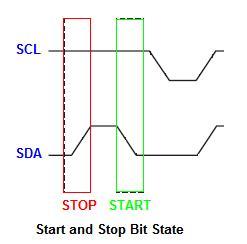
STOP Condition
The Stop Data Transfer is initiated when there is a change of state of SDA line from LOW logic to HIGH logic while the SCL line is at HIGH logic. This is the STOP condition.
DATA Transfer Condition
The data transfer is done between the START and STOP conditions with the data being transferred when SCL transition from LOW to HIGH logic. Data is read when SCL is at HIGH logic. SDA line data will only change when SCL line is at LOW logic. There is no limit to the number of data bytes transferred and is determined by the master device. Acknowledgement of successful transfer of data is done between the master and the slave devices at regular interval.
Fundamental And Types Of Capacitors

Introduction To Capacitors
A capacitor is a body which can store an electrical charge. It consists of 2 conducting plates facing each other and separated by an insulating material. This insulating material is also called dielectric material. When a charge is stored in one plate, an equal and opposite charge is inducted on the other plate and thus a potential difference is set up between the plates.
The unit of measurement for capacitance is Farad but this unit is much too large for practical work. It is usually measured in microfarads(uF) or picofarads(pF). The formula of calculating capacitance is
C= [(0.224 KA)(n-1)]/d where
C = capacitance in pF
K = dielectric constant of material between plates
A = area of one side of the plates square inches
d = separation of plate in inches
n = number of plates
The potential difference V developed when a charge Q is stored depends directly on the value of Q and inversely with the capacitance C of the cap.
V = Q/C
They are used in timing circuits as it takes time for a cap. to be charged up. They are used to smooth varying DC power supplies by acting as a reservoir of charge. They are also used in filter circuits because they easily pass AC signals but they block DC signals.
DC Voltage Rating
The DC working voltage of a cap. is the maximum voltage which may be applied continuously on the electrodes of the cap. at the upper limits of the working temperature range. The peak value of an alternating voltage should not exceed this rating and have to be derated according the the FMEA as recommended in FMEA
Leakage Resistance
The dielectric of a practical cap. introduces power losses which can be represented by a small resistance connected in series with the cap. The insulating resistance is often greater than 3,000 Mohm.
Types Of Capacitors
There are many different types of cap. that are used for different types of applications. They are electrolytic cap., ceramic cap., tantalum cap., polyester cap., polystyrene cap. and safety cap.(namely X and Y types of cap.).
Electrolytic Type
Electrolytic cap. have leads that are marked with + or - signs. They have polarity and must be connected with the correct polarity. The values of the capacitance and voltage rating are are printed with on its body. The voltage rating can range from 5V up to 440V DC. Generally this type of capacitor is used as smoothing cap. in power supply regulation. The bigger the value of the cap. is, the less ripple the DC supply that has been rectified will be.
Ceramic Type
This type of capacitor is most commonly used and both through hole and surface mount types are available. Its application is mainly used in general digital circuit, as power supply bypass capacitor, converters (both for input and output), Smoothing capacitors, DC-DC converters, Switching power supplies (secondary side).
Figures below show the typical characteristics of this type of capacitor. It shows the construction and the temperature range and codes of the cap. The impedance vs frequency change is also shown.


Tantalum Type
Tantalum type have low voltage ratings and they are expensive but very small. Usually they are used in application where a large capacitance is needed in a small size.
Metallized Polyester Film Type
Metallized Polyester Film is used for general purpose applications. Some of the features are its Self-healing property and flame retardant epoxy resin coating. Its voltage ranges from 100V DC to 1250V DC.

Safety Type
This type is classified into classes like X and Y types. It is usually used on the live parts of the circuity. One of the applications is in the area of reducing the harmonics on inverter motor drives type of application. As safety is a main concern over here, usually this type of cap. has UL, VDE, SEMKO and other types of marking which certifies that it conform to the safety standard of a particular country.
Fundamentals of Batteries

Introduction
Batteries can be divided into two categories. The primary type is intended for one time use only and is disposed after the charge has dropped to a level that cannot be used. Primary type should not be discharged as heat will be generated within sealed cells. It will also damage the equipment as a consequent of fluid leakage. The storage or secondary type can be recharged many times and is reusable.
The rating of its capacity is ampere hours (Ah) which is a product of current drain and time.
If it become cold, it will have less charge available and some design to keep it warm before use. It may lose 70% of its capacity at cold extremes but will recover with warmth.
Primary Batteries
Carbon zinc is the most common primary cell in which the chemical oxidation converts the zinc into salts and electricity. When there is no current flowing, the oxidtion stops. If keep for a long period of time, the stored batteries will degrade and dry out where it will no longer able to supply the desired current. The time taken for the degradation without being used is called shelf life. It has a nominal voltage of 1.5V.
Alkaline types have longer capacity at low temperatures. Lithium type have nominal voltage of 3V/cell and has the best capacity, discharge, shelf life and temperature characteristics. Its setback is the high cost.
Silver Oxide and Mercury has voltages of 1.5 V and 1.4 V respectively and are used where constant voltage is desired at low currents over a long period of time. Their main used and applications are in hearing aids.
Storage Batteries
The most commonn type is nickel-cadmium(Ni-Cd) type with a nominal voltage of 1.2V/cell. If used carefully, it can be rechargable up to 500 times compared to alkaline type which is 50 times or so. The most widely used storage type is the lead-acid type in automobile.The lead acid battery is made up of plates, lead, and lead oxide with a 35% sulfuric acid and 65% water solution.
Gas escaping from it may be explosive and always keep flame away. It should not be subjected to unnecessary heat, vibration or physical shock. Frequent inspections for leak is recommended. The electrolyte is chemically active and conductive and may ruin electrical equipment if leaks occurred. Its acidity may be neutralized with sodium bicarbonate or baking soda.
In order to ensure that all the cells in NiCd reach a fully charged condition, it should be charged by a constant current of 0.1 C current level. It is around 50 mA for a AA size cells. Charging should be terminated after 15 hours at the slow rate. A built in circuit that will stop charging when 1.43V/cell is reached will enhance the life of the battery.
Electronic Ballast Design Project
Fluorescent Lamp was introduced commercially in the 1940s and was a success in small scale lighting replacing the use of tungsten incandescent bulb. It continued to be used in the 21st century and has since evolved into many variation of outlook, applications and control.
Two main functions of a fluorescent lamp ballast are providing a starting kick and to limit the current to its operating value for the tube that is being used. There are basically 2 types of ballasts namely magnetic ballast and electronic ballast design. The magnetic ballast uses a core and coil assembly transformer that provides a minumum functions of starting and operating the lamp. Hence it is not as efficient as the electronic ballast. Electronic ballast operates at high frequencies from 20kHz to 45kHz and uses electronics circuitry to optimize the operation of the lamp.
Instant start ballasts require an instant-start certified lamp and ignite a lamp in about 80 milliseconds or less using a high frequency electronic circuit. It starts the lamp without heating the cathodes by using a high voltage at around 600V. It is the most efficient energy type when used in installations where the lamps are not turned on and off regularly.
Rapid start ballasts precisely heat the cathodes and then ignite the lamp with a lower charge. In this way, it helps to prolong the life of the lamp but it uses more energy as the cathodes are heated up continuously during the operation of the lamp.
Programmed Start is an upgrade version of rapid start. It allows the cathodes to be preheated before applying the voltage to the lamps to strike an arc. This type gives the best life to the lamps and is used in applications where frequent ON/OFF of lights are required.
Electronic ballast must be designed, installed and operate in compliance with the CSA, UL and NEC requirements. As the installation and testing come in contact with hazardous voltage, only qualified personnel should perform the installation. It should be done with the power to the lamp turned OFF.
Compact Fluorescent Lamp (CFL) Electronic Ballast Design
One of the advancement made in the field of electronic ballast control is the invention of compact fluorescent lamp or CFL in short. It is also known as energy saving lightbulb and is usually screws into the standard light bulb socket or plugs. Common screw type size used is E27. Compared to incandescent bulb, it have a longer rated life and uses less electricity though its initial cost is higher.
Two main parts to a CFL are the gasfilled bulb and the electronic ballast. Electrical energy flows though the gas causing it to give off ultraviolet light(UV light) that excites a white phospor coating on the inside of the tube. This coating emits visible light. A typical CFL is shown below
Electronic ballast design is becoming more common due to its superior performance. It outputs 10%-15% more light output, does not have the 50/60 cycles irritating hum, high frequency switching that does not have visible flicker to the human eyes, cooler and more reliable. Though its initial cost is higher than the magnetic ballast, its payback will come in the long run. Operating the ballast at higher frequency means that the design can be smaller and made compact. It utilizes the switching mode power supply technology in its implementation.
Magnetic and electronic ballasts can be categorized into 3 categories - instant start, rapid start and programmed start.
