LEDs Fundamentals and Applications
Introduction to LEDs
The primary component in optoelectronics are the LEDs. Light emitting diode is a diode with PN junction of crystal material that produces luminescence around the junction when forward bias current is applied. The junctions of this light emitting diode are made from Gallium Arsenide(GaAs), Gallium Phosphide(GaP) or a combination of both(GaAsP).
The available colours are red, white, yellow, green and blue.Some are housed in plastic affixed to the base header of a transistor package. Others are contained in plastic packages that have a dome shaped head at the light emitting end. Two wires protrude from the opposite endfor applying forward bias to the device.
These days, surface mount types are commonly used.
One of the typical example of its application is as shown below.

The forward bias current of a typical LED ranges between 10 and 20 mA for maximum brilliance. A 1 kohm resistor in series with a 12 V DC source will caused it to operate at 12 mA. In order to ensure the lifetime of it is preserved, do not exceed the maximum rating of the current. The voltage drop across it is typically 1.8 to 2.0 V DC.
Absolute Maximum Ratings at 25° Celcius
Reverse Voltage = 5V
Forward Current = 20mA to 30mA
Forward Current Peak at 1/10 Duty Cycle, 0.1ms pulse width = 100mA to 150mA
Power Dissipation = 100mW to 150mW
Operating Temperature = -40° Celcius to +85° Celcius
Storage Temperature = -40° Celcius to +85° Celcius

Operating Characteristics
Typical Forward Voltage at 20mA = 1.7V to 2.0V
Maximum Forward voltage at 20mA = 2.5V
Reverse current when 5V reverse voltage is applied = 10 uA
Peak emission wavelength at 20mA = 627nm to 700nm (value depends on the colout of the LED)
Spectral line half width at 20mA = 20nm to 45nm
Capacitance at 0V forward voltage and (f=1MHz) = 35pF to 45pF

Manual Soldering of LEDs
Soldering tool wattage should be less than 30 Watt.
Soldering temperature should be less than 300 °Celcius.
Soldering time should be less than 30 seconds.
Fundamentals of Diodes and Their Applications

Introduction
There are many types of semiconductor diodes namely Selenium, Germanium and Silicon types. Selenium type is commonly used in the early days in ac power suppliers but in recent years it has been replaced by silicon type as it sometimes emit toxic fumes when it burnt out. The characteristic is that it allows current to flow in one direction as shown in the symbol below. It has a cathode and a anode which determine the flow of the current. Current can only flow from anode to cathode.
![]()
Silicon V-I characteristics are shown in the figure below. The junction barrier for silicon is about 0.7V and for Germanium is about 0.3V. It is also called forward voltage drop. Most of the diode used today are of silicon type as they are robust and reliable from DC to RF small signal applications.
Types of Commercially Available Diodes
In small signal application of which the current requirement is less than 100mA, 1N4148 is a typical choice. It has a forward voltage drop of 0.7V and is made from Silicon type.
In recifier circuit applications, the typical ones used are 1N4001 to 1N4007 for current rating of 1A and 1N5401-1N5408 for current rating up to 3A. The table below shows the devices and their maximum reverse voltage ratings.
Diode
MaximumCurrent
MaximumReverseVoltage
1N4001
1A
50V
1N4007
1A
1000V
1N5401
3A
100V
1N5408
3A
1000V
Digital Temperature Sensor

Digital Temperature Sensor
The use of temperature devices in temperature measurement and sensing have made tremendous progress in the last few decades. There are a few types of measurement solutions that you can implement in your projects. The use of thermistors or thermocouples are the two most widely used devices in measurement solutions. The recent decade has seen the use of integrated circuits devices in many temperature control related systems because they are much smaller, provide a more accurate measurement and simpler to be integrated to other digital control devices.
Most of the digital temperature sensor system has a built-in communication bus to enable it to communicate with the master control IC. The most used communication interface is called I2C, a simple bi-directional 2-wire bus that was developed by Philips Semiconductors in the 1980's. Since then, many devices has this built in communication protocol that enables all devices that have this feature to be linked together without any other additional components. The I2C interfacing standard has become a world standard that are used in more than 1,000 integrated circuits.
I2C In Brief
The I2C standard basically define the start, stop, device selection addressing and data transfer interfacing protocol. The hardware consists of 2 I/O lines called SDA and SCL lines.
START Condition
The Start Data Transfer is initiated when there is a change of state of SDA line from HIGH logic to LOW logic while the SCL line is at HIGH logic. This is the START condition.
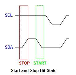
STOP Condition
The Stop Data Transfer is initiated when there is a change of state of SDA line from LOW logic to HIGH logic while the SCL line is at HIGH logic. This is the STOP condition.
DATA Transfer Condition
The data transfer is done between the START and STOP conditions with the data being transferred when SCL transition from LOW to HIGH logic. Data is read when SCL is at HIGH logic. SDA line data will only change when SCL line is at LOW logic. There is no limit to the number of data bytes transferred and is determined by the master device. Acknowledgement of successful transfer of data is done between the master and the slave devices at regular interval.